|
|
Allready set a bookmark? |Mendocino-Motor| |
||||||||||||
|
|
|||||||||||||
|
|
Preface |
|
| The Mendocino motor is a solar-powered magnetically-levitated
electric motor. |
||
|
|
Schematic construction - Mendocino Motor |
|
 |
||
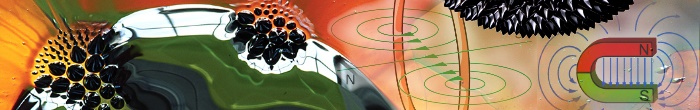
| Schematic construction of the Mondocino - Motor: The both colors red and green are symbolize for the poles of the magnets. Red for the North Pole and green is the South Pole. The round magnets are for the levitating and the square magnet for the rotation. The rear brace is holding the rotor. For a very low friction is the shaft end taper to a point (HSS-drill) and goes on a mirror. | ||
 |
||
| The schematics of the Mendocino - Motors:
Altogether we have four solar cells arranged in a square. The upper cell
shows to the light and the opposite (downsite) shows in the shadow. We
have two cells connected in series. It looks like mysterious because there
will be have a short circuit. Practice has shown that is functional. It´s
always one of the both cells go into action and it build up a voltage.
The cell in shadow site is closed and a current will flow over the rotor
winding. We turn the rotor to the opposite (180°) and this coil have
a reversed polarity. This produced magnetic field which interacts with
the field of the magnet under the rotor. This interaction causes the rotor
to turn. As the rotor rotates, the next solar cell moves into the light
and energizes the second winding. This process repeats as the motor spins.
In my example I have used solar cells (65x20mm) with a half volt output and a current of 250mA. The strength of magnetic field (Durchflutung / magnetomotive force) is the product from the number of turns in the winding and the current in the wire. For a "high" electricity flows we need a "thicker" copper wire. I used a coil with 100 windings and a thick from 0,22mm (lacquer-coated wire). The resistor is 9 Ohm. The current, a product of, voltage (V) and resistor (R): I=V/R = 0,5/9 = 55mA and that is enough. That ist what we need as a minimum for your solar cells. My cells have 250mA at sunlight. Unfortunately, the power goes down with decreasing sunlight. For that reason we need any reserves for it. |
||
 |
||
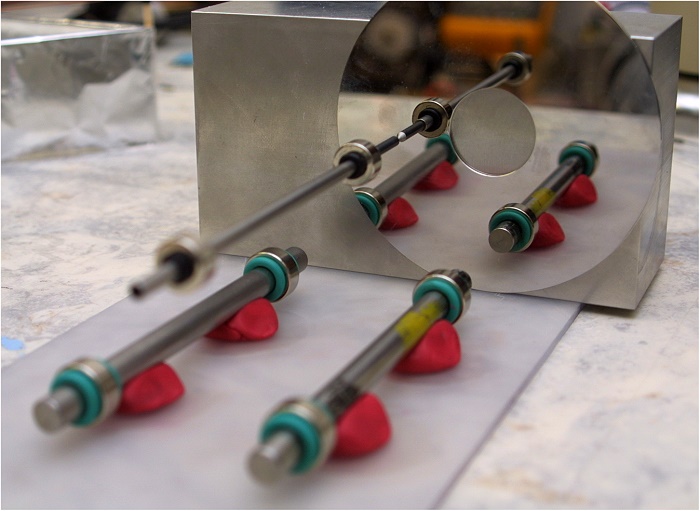
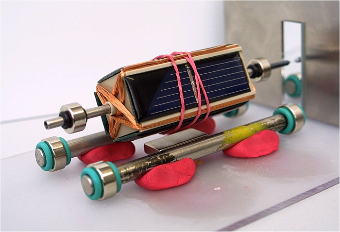
| Here my first try to levitate. All magnets are neodymium-magnets. | ||
 |
||
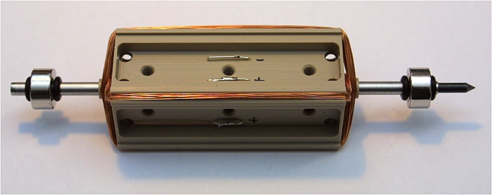
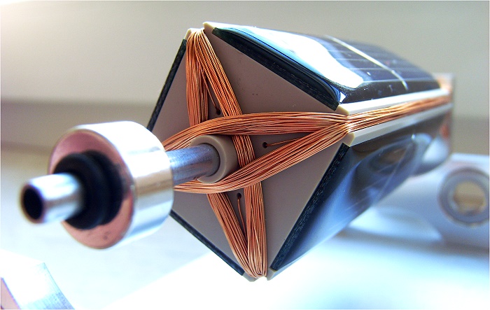
| Now the motor armature on the shaft: The silver wire go through the shaft to connect the solar cells. For balancing it i made three tapped holes for grub screws. So it´s possible a fine adjustment. | ||
 |
||
| So let's go and check out if their all be ok? On the top you can see a very thick copper wire it´s also to balancing the rotor. I never believed that the weight of the cells are so different. | ||
 |
||
 |
||
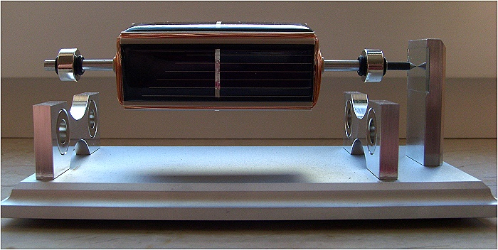
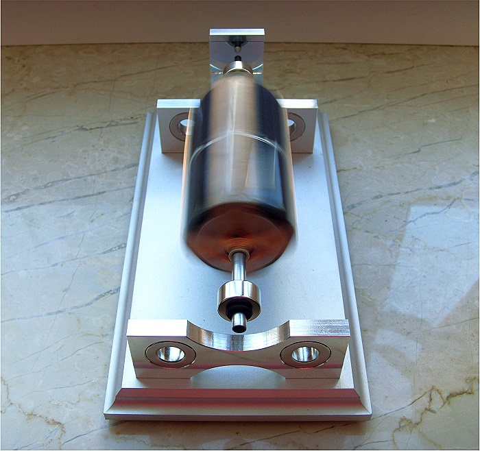
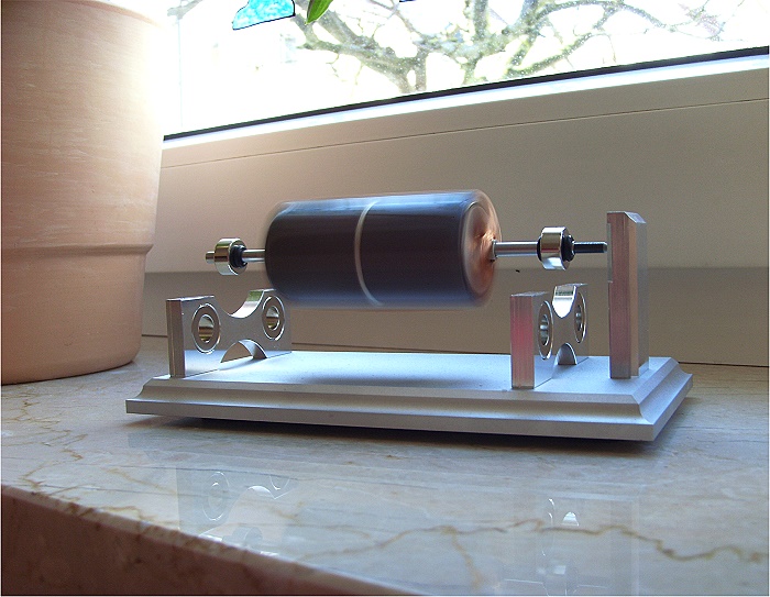
| And finaly the Mendocino - Motor on my windowsill. | ||
 |
||
| Now running. | ||
 |
||
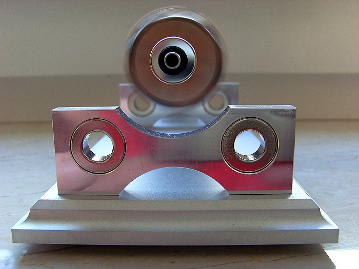
| The frame is milled from aluminium and screw connected. | ||
 |
||
| Here you can see how the wire goes to the mount inside. | ||
 |
||
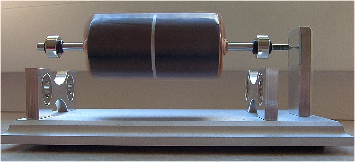
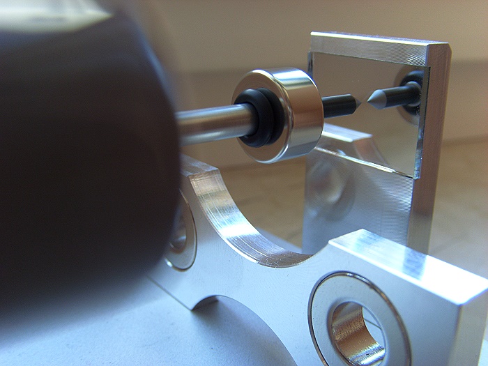
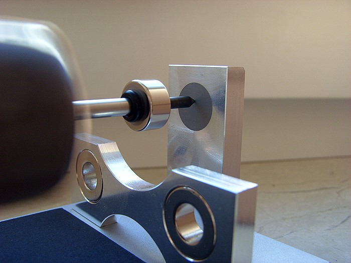
| On the opposite the mirror for a low friction. The mirror is glued to the brace. | ||
 |
||
| Top view. | ||
 |
||
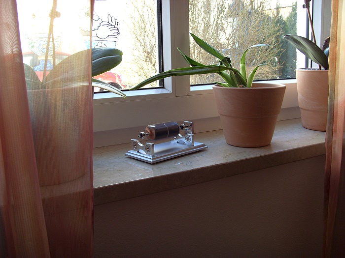
| With flowerpot. | ||
 |
||
| And now with two flowerpots :-) | ||
|
|
Version 2 |
|
 |
||
| I am sorry to say that, so far, the tip of the
shaft has bored into the mirror. These lead to a deterioration of the
running properties. In the weak light the mondocino motor can´t
start to run and in addition it started to reel. Conclusion: First my mirror had to be removed and must be replaced by a very hard material. I found a ceramic indexable inserts (Polycrystalline Boron Nitride Indexable Inserts - PCBN). The most mendocino motors has a mirror to hold the rotor but there use ballpoint refills. This is much softer than my 3mm HSS-drill. It remains to be seen how it work. Supplement : Half a year after, the motor is always running. It´s nothing to see on the PCBN ;-) |
||
|
|
Video |
|
|
|
||
|
|
Allready set a bookmark? |Mendocino-Motor| |
||||||||||||
|
|
|||||||||||||
Fatal error: Uncaught Error: Call to undefined function mysql_connect() in /www/htdocs/w00cc458/php_kommentar/vionlink_comments/db_vbdg.php:32 Stack trace: #0 /www/htdocs/w00cc458/projekte/magnet/english.html(451): include() #1 {main} thrown in /www/htdocs/w00cc458/php_kommentar/vionlink_comments/db_vbdg.php on line 32