Already set a bookmark?   |Floating sphere|

Twitter Facebook Google Mail Fav


Preface

Anti-gravity is the idea of creating a place or object that is free from the force of gravity. It does not refer to the lack of weight under gravity experienced in free fall or orbit, nor to balancing the force of gravity with some other force, such as electromagnetism.
Magnetism is fascinating, especially when it is used to cause objects to levitate or float or be suspended in the air, defying the gravity which keeps us on the ground. How can this be done? Well, look my self made magnetic levitator :-)


The floating sphere

 
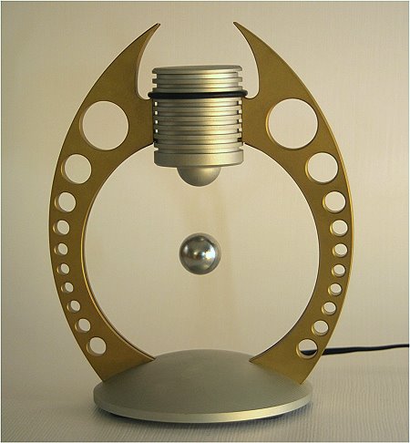
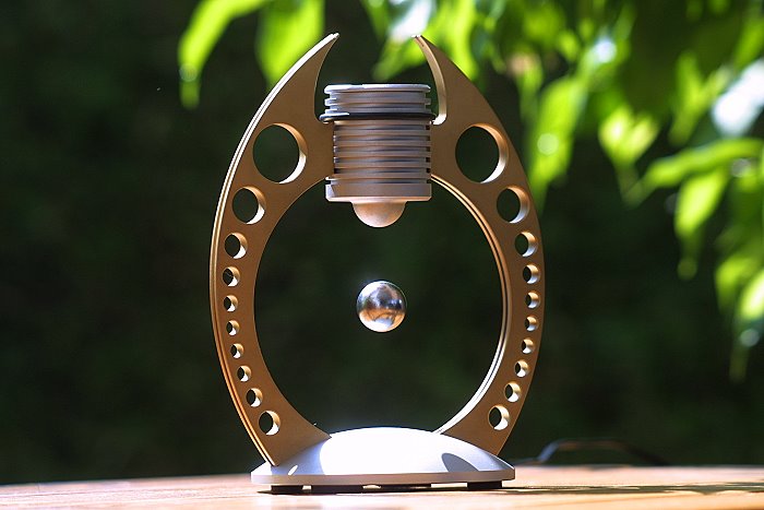
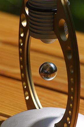
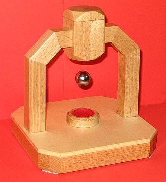
Here I present a suspension device in which a neodym magnetic sphere levitates. The electronics are in the pedestal and on top is an electromagnet with sensor (SS495A). The voltage supply comes from an external power supply unit with 15V direct current.


The machanical structure

 
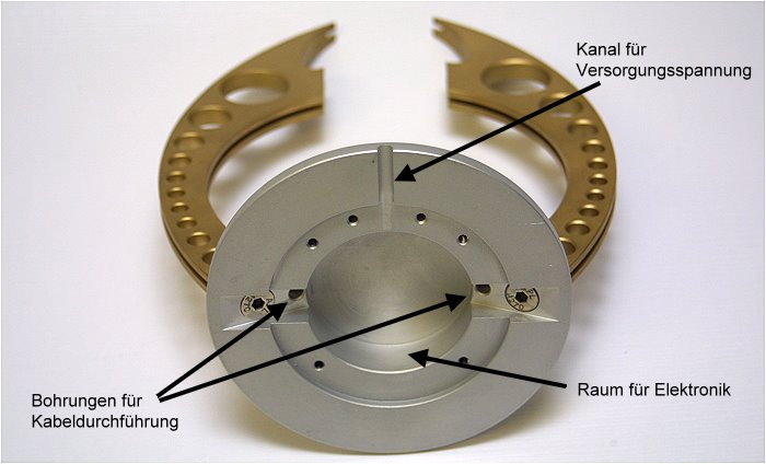
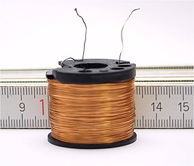
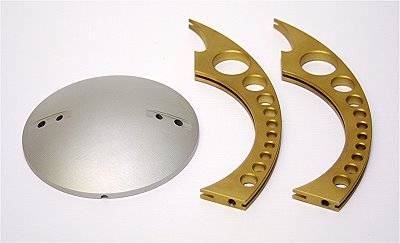
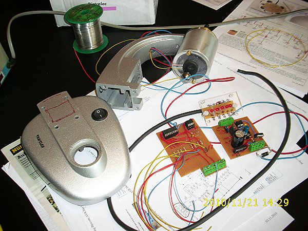
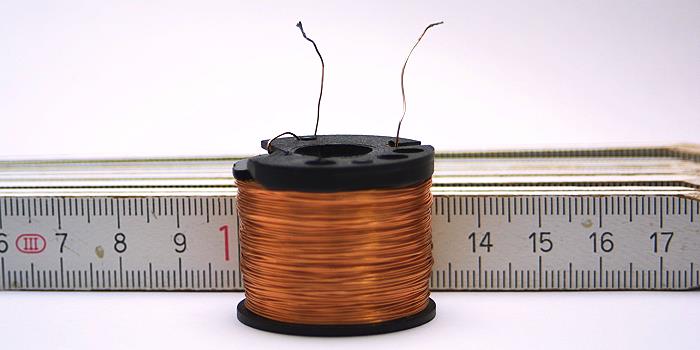
Left Picture: The coil (electromagnet) is the heart of the Levitron (see magnetic flow density in coils).

Right Picture: Here you can see the aluminium base plate with a 99 mm diameter and the two brass bearers.

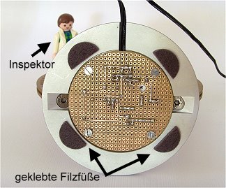
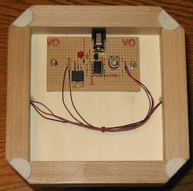
View from below: Here is room for the electronics on the breadboard plate. The cables for supplying the cupola go through the boreholes (sensor & coil).

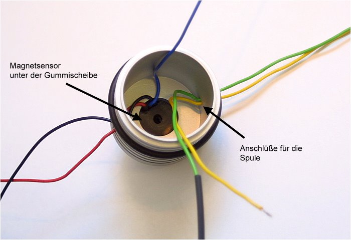
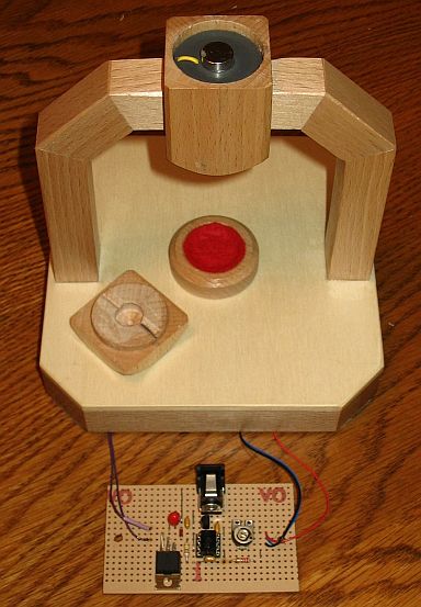
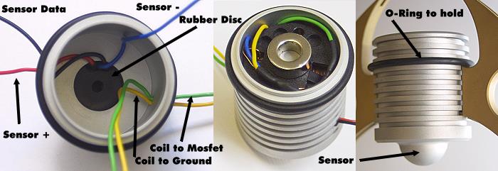
The dome: From aluminum milled. View inside the socket: The Hall sensor is fastened in the tip of the socket with a rubber disc.

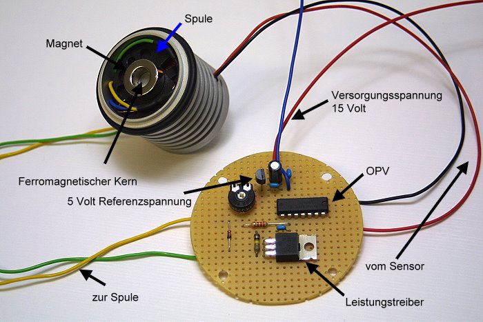
A view on the inside: The electromagnet with magnetic field sensor and neodym ring magnet in the aluminium socket (left). On the right the circuit board.

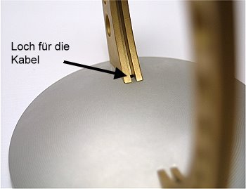
Left photo: The circuit board was fastened from below with four M3 screws.
Right photo: Grooves in the brass bearers (6 mm deep, 2 mm wide) to hide the cables that run upwards.


The circuit diagram and schematic construction

 
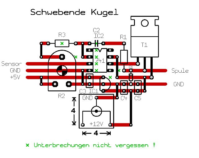
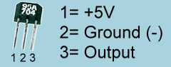
Here the circuit diagram of the levitron. On the left side you will see a 5Volt-Regulator 78L05 ( see data sheet) this is the power supply for the hall sensor SS495 ( see data sheet) it is also used as referece voltage for the op-amp. With the adjustable resistor (R2) you can change the distance between flying object and coil.
The op-amp UA741 or LM348 ( see data sheet) is to see as differential amplifier.
The coil (L1) is attached to the high-power driver P-channel MOSFET IRF4905 ( see data sheet) to amplifying the output signal from op-amp. We should protect the MOSFET from the coil's kickback voltage. When its magnetic field collapses as the output MOSFET turns off, a high voltage spike is generated. This can easily overcome a MOSFET's maximum breakdown voltage. So we provide a protection diode (D1) across each coil, which passes current to keep its forward voltage drop down to about 0.7v.
I use a bench style adjustable regulated and metered dc power supply. The maximum switched current was 500mA.
With levitating magnet need this circuit 60mA only and without magnet the current increases to maximum. That is too much for this coil and she warm up. So you can´t use it for permanent operation. For a safe operated you will need a current limiting.

The functional principle:

An electromagnet (coil) is turned on. The magnetic sphere gravitates towards it. When the sphere gets near the magnet sensor (Hall sensor), the sensor reacts and turns off the electromagnet. In the following, the sphere descends again. The magnet sensor then turns the electromagnet on again and the cycle starts anew. This happens approx. 70 times per second (depending on the distance and the weight of the magnet). That's how the magnet levitates.


Photos

 
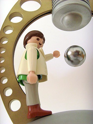
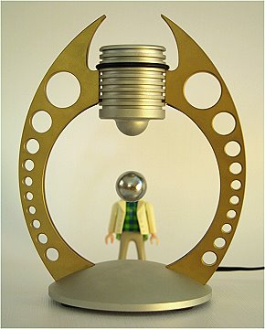
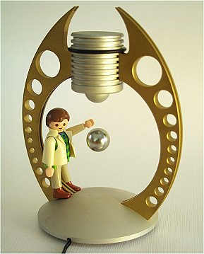
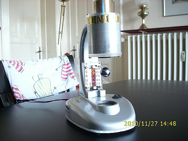
The cupola with the coil and the sensor is only lodged between the brass bearers. An o-ring (black) provides additional stability. The Hall sensor SS495 is situated in the small "bump" below. The cupola is closed with an aluminium lid.
Also playmobil character Bernd has fun with the Levitron.

Wow.

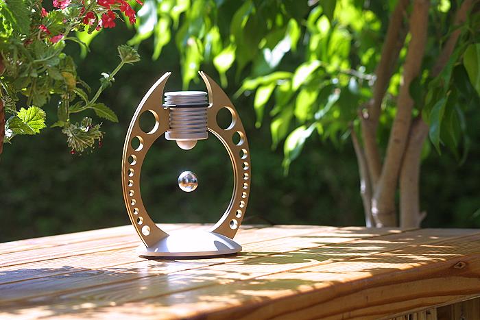
In the garden, already very decoratively!
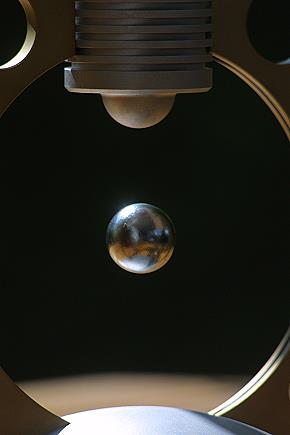
Slightly larger!

Fascination floating: I can't get enough of this!


Circuit diagram


Video      My channel at YouTube


Already a set bookmark?   |Floating sphere|

Twitter Facebook Google Mail Fav


Other constructions


   Levitron by Bernd:

- As frame a old microscope
- Larger coil (wire 0,28)
- Floating distance greater 1"
- Cool Gauss-Display
- Frequency 30Hz


Levitron by Mikado:
This Levitron is made from beech wood. The wood profiles are 0.78 inches in a square and in the middle a hole for the cable to connect the coil.


Comments and questions (12)


  • Comment by dario 09.02.2012, 19.22

    hello again, thanks very much for you reply...
    I only have here the UGN3132U or KMZ41 or SS549AT or TL172

    Answer: Hello, it is really difficult. I don't understand the datasheets from your components.

    For the best results you need a analog output. The SS495 has a supply from 5V and a output from 2,5V (without magnet field). That ist the half of supply power. Comes a magnet field in the near, the output change to high or low, depends from magnetic pole. The sensity is 3,125mV per gauss and the absolutly range is -670 to +670 Gauss or -67 to +67mT. In the datasheets from your components, I missing this information. So I'm not sure if it works.

    Or you can take a digital output (Schmitt trigger) like the TLE4905L/TLE4935L. This switches on at 18 mT. I think the TL172 is good but this need 7V. The UGN3132U is also a candidate for testing.


  • Comment by Dominic 03.02.2012, 18.26

    I saw a large version of this at Cal Poly (college) in San Luis Obispo (central coast of California, USA) in the late 1960's at their annual festival 'Poly Royal'. Thanks for showing me what they did. Theirs was 4' high, and the suspended item was a steel globe of the earth. Weighted at the bottom, it sat there spinning slowly. Even got the direction of rotation right. Very clever. Thanks for the diagrams.

    Answer: You're welcome


  • Comment by dario 02.02.2012, 18.05

    hello again, I can get the AH211 TWO PHASE HALL EFEECT is possible put this

    Answer: No, the AH211 is not suitable but you can take the TLE4905.


  • Comment by dario 01.02.2012, 20.22

    hello from argentina bs as, south america, thanks for this grat projet, here is very dificult to find the SS495A sensor is possible put some other do you have ideas?


  • Comment by Roy 22.12.2011, 00.35

    Hi

    The resistor R1 and capacitator C2, what is it for?
    Has it something to do with the frequency ??
    Sorry i am just curiuous :P.


  • Comment by Ramon 21.12.2011, 09.57

    Hello.

    Where I can get the coil.?

    In the event that the build myself, where the ferromagnetic core bag?

    Thank you and congratulations on the project.

    Answer: A coil to find , that is really a problem. You must be creative. Either self made or looking at ebay.
    The ferromagnetic core is very simple. You can take a big nail or other magnetic steel.


  • Comment by Eric 16.12.2011, 23.31

    Hello,
    May i ask you why there is a feed back?
    I dont know what it really does.


  • Comment by Damien 13.12.2011, 00.30

    How much is it cost ??

    Answer: Itīs unsaleable :-)


  • Comment by Catalin 18.03.2011, 09.32

    Hi! Nice project. Very simple circuit compared to others I have seen. Could you explain me the role of the magnet on the top, and the role of R1, C2?
    I have tried it without the magnet on top (I didn't have one), but the flying magnet strongly oscillates at low frequency (just a few Hz) and does not stay into a fixed position.
    Thanks!

    Answer: Well, itīs not easy to explain the role of the magnet on the top. First, it will work without this magnet but the floating distance will be smaller. For the best result you must try it.
    The resistor R1 and the condensor C2 are a feedback-loop and stabilized the work of the coil.
    If your magnet oscillates is your magnet too heavy or the coil to small. Take one a smaller magnet and the frequency will be higher or you boost the power supply.


  • Comment by Willem 13.02.2011, 10.32

    Great project. I could not find the connections of the SS495A in datasheets available on the Internet.Could you tell me which leads (1-2-3) correspond with +V - GND - OUT?

    Answer: That's really a problem. I also couldn't find it in datasheets and I try to found the connection at the time.


  • Comment by Luis email 04.01.2011, 21.04

    Oh, my email is ttnemk@hotmail.com
    thanks!


  • Comment by Luis again 04.01.2011, 21.03

    Hi, its me again, I found the english version. How about posting a video showing how to make the coil connection to cables and the circuit board? Im actually interested in building a floating Globe, with just a base magnet and a magnet holder inside the Globe. I dont think the upper part of your device is needed if you have a flat top. Thanks.

    Answer: The connection is very simple. I have it hidden in the brass bearers. One side is the cable for the coil and the other side for this sensor. You can see it on my pictures. A tutorial video is too many work :-)

    Now to your floating globe project. Thatīs right, you need only any base magnets and coils to floating a globe (and one into the globe). This is one of a future project for me. Are you interest? i have a good site (check this).
    First i would tried floating a magnet (two or four magnets on a plate), like my mendocino-motor (check my other projects). Now the plate with this magnets will brake out to a side, now you take a coil with sensor (one of each two sides) and use this circuit, i have used, to regulate the position. Thats all! I hope so, i dont have try it.
    Have you the first results of this, let me know it. Good luck!

  • Name (required)
    Vorname
    Your comment or question (required)
    Email
    Homepage
    Telefon

    Sicherheitscode*


    Last update 18.03.2011

    bis0uhr@gmx.at